


In the future as well, generation of electrical energy from wind power will contribute a lion’s share to the energy revolution. The operating safety of wind power turbines is thus of central importance. Professional test technology assures that the large investments required for the expansion of this technology will pay off, and that the reliability demanded by the insurance carriers is retained over its entire service life.
In 2017, the entire European Union generated more electrical power from wind, sun and biomass than from semianthracite and brown coal for the first time. In the meantime, renewable energy sources account for 30% of all electrical power generation.
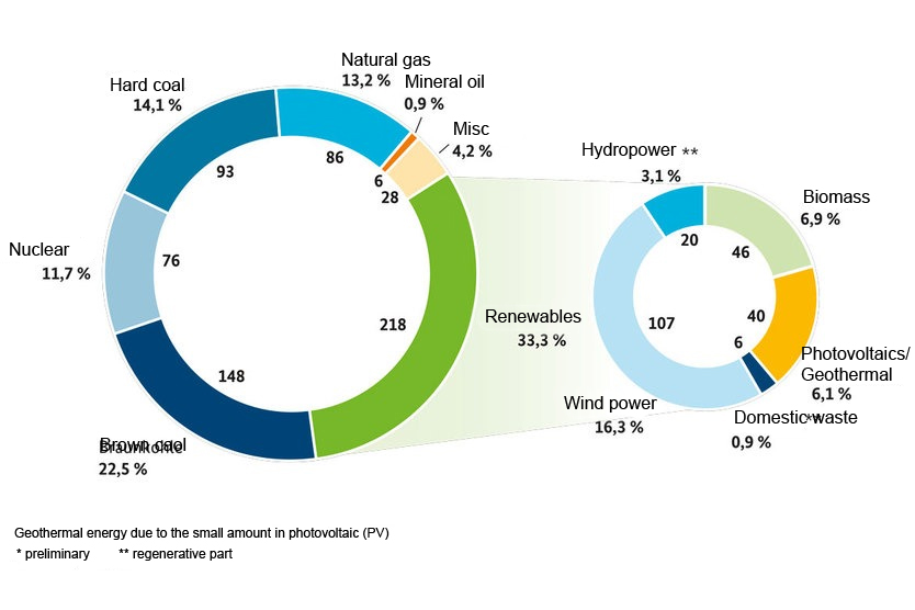
Figure 1: Gross electrical power generation in Germany in 2017 in TWh, preliminary data, estimated to a given extent, ** renewable share, revision level: February 2018 © AG Energiebilanzen, source: BMWi
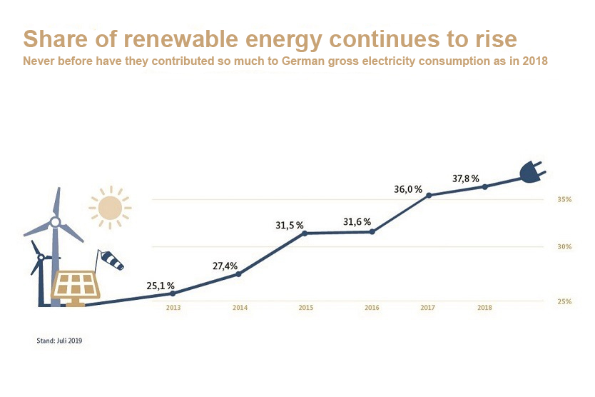
Source: BMWi (https://www.bmwi.de/Redaktion/DE/Infografiken/Energie/anteil-erneuerbarer-energien-steigt.html), revision level: 2018
With power generation amounting to more than 217 billion kWh, the renewable energy sources further increased their lead relative to conventional energy sources in 2017. A total of 36% of all energy requirements in Germany were fulfilled by wind power, solar power, biomass, water power and other renewable energy sources, to which the sharp rise in wind power generation made a decisive contribution. Both onshore and offshore, more than 103 billion kWh of wind power were produced, and new wind power turbines with total power amounting to more than 5500 megawatts were connected to the grid. Wind parks are laid out for decades of use and have to assure reliable long-term operating performance. Undetected damage can have serious consequences all the way up to the complete failure of a system if, for example, a defective turbine results in a short-circuit and causes a fire in the nacelle, which on the average is installed at a height of 120 meters.
TECHNICAL TESTING CHALLENGES
Additional challenges for testing these systems result from the increase in technical electrical components that make operation possible with voltages of greater than 400 V, which is the prevailing level in large portions of the public supply network. Suitable solutions with frequency converters and new, high-power generators make the transition from 400 to 690 V AC attractive for wind power generation, especially for systems with nominal power as of 600 kW. Due to the fact that energy loss is reduced at higher voltage levels, considerable increases in efficiency are made possible while reducing costs for cabling and operation at the same time.

Test technology has to do justice to this development through the use of instruments which can reliably handle all of the required measurements in the low-voltage range in compliance with the standards. As the only supplier on market thus far, measuring technology specialist Gossen Metrawatt has developed a test instrument with which testing can be conducted in 690 V AC as well as 800 V DC networks for the first time ever. And due to the fact that voltages of up to 1000 V AC / 1000 V DC can also be measured with the standard version of the PROFITEST PRIME, a single instrument is all that’s needed in order to test the safety of photovoltaic systems and wind power turbines in addition to control cabinets, machines and industrial systems.
LEGAL AND NORMATIVE REQUIREMENTS
According to German occupational safety law (BetrSichV), power generating systems operated as closed electrical service locations must be tested for electrical safety in accordance with the requirements set forth by German public accident insurance (DGUV). According to DGUV regulation 3, the interval between two tests conducted on electrical systems and stationary operating equipment which are subject to normal stress due to ambient temperature, dust, humidity and other comparable environmental influences should not exceed four years. The tests, which have to be arranged for by the system’s operating company, must be performed under the direction and supervision of a qualified electrician, who certifies that the system is in good working order before initial start-up and after any modifications or repairs.
Requirements for safety and reliability with regard to energy supply are specified in part 6 of the German energy law adopted in 2005 regarding the supply of electrical power and gas (EnWG, 2005). Section 49 of this law stipulates that energy systems must be set up and operated in accordance with the generally recognized codes of practice which are listed as examples in the VDE requirements for the generation, transmission and discharge of electricity. This includes protection against electric shock and the effects of current on human beings and livestock from the VDE 0140 series of standards, and the selection and erection of electrical equipment, switchgear and controlgear, as well as earthing systems, protective conductors and protective measures against electric shock from the VDE 100 series of standards. This is supplemented by testing the safety of machines in accordance with DIN EN 60204-1 (VDE 0113-1) and lightning protection systems in accordance with DIN EN 62305-3 (VDE 0185-305-3, supplementary sheet 3). The exact scope of testing is specified by the responsible electrician, for example on the basis of a hazard assessment in accordance with section 3 of the German occupational safety law adopted in 2015.
METROLOGICAL TESTS
Testing of protective measures begins with a general visual inspection, during which all cables are examined for correct type and laying, and electrical components are checked for secure mounting, as well as correct connection, labelling and dimensioning. This is followed by testing of the effectiveness of protective measures, and function tests. Approved measuring instruments for testing, measuring or monitoring protective measures in low-voltage systems with up to 1000 V AC must be used for reliable performance of the measurements in accordance with DIN EN 61557/VDE 0413. For the protection of the inspector, only those instruments should be used which, according to their measuring category, are suitable for the respective applications in accordance with IEC 61010-1. During the course of initial testing, all measuring points must be checked and logged in order to conduct a complete examination of the electrical system, to verify installation in accordance with the standards and, if applicable, to ascertain any installation errors. Periodic testing serves to verify that the examined system, including any modifications, is in safe working order, and to detect any manipulations. Core testing tasks include:
1. Measurement of Voltage and Phase Sequence ...
... for verification of the electrical system’s functional safety. It must be assured that fuses, as well as single-pole control and protective devices, are only connected to the phase conductor and that cables and wires have been properly connected to the electrical operating equipment. If required, the system’s input voltage polarity must be checked before initial startup.
2. Continuity Measurement at Cables and the Protective Conductor ...
... by means of resistance testing for protective conductors, equipotential bonding conductors and, if applicable, conductive parts, in order to verify compliance with breaking requirements and automatic shutdown of supply power. Resistance is measured for each protective conductor system between the PE terminal and all relevant points, which are part of each protective conductor system. Due to the fact that amperage used for testing should be adequately small in order to rule out any danger of fire or explosion, resistance is measured with a current of between at least 0.2 A and approximately 10 A. Verification is deemed successful if the measuring instrument reads out a suitable value in light of the respective protective conductor’s length, cross-section and material. No maximum permissible resistance value is specified, but the measured values should not exceed the conductor resistance which corresponds to the cable length plus the usual contact resistances. The following reference and empirical values apply: < 1.0 Ω for the protective conductor system and < 0.1 Ω for the equipotential bonding conductor. The measurements can be performed using various test currents with the PROFITEST PRIME. Furthermore, 4-wire measurements are possible with 200 mA for cables with lengths of up to 70 m and cable cross-sections of 2 x 0.5 sq. mm with automatic polarity reversal.
3. Insulation Resistance Measurement ...
... in order to verify good working order and the fulfillment of promised performance in the case of new installation or approval of an electrical system. Good insulation resistance assures safe, efficient, loss-free operation of electrical systems, and at the same time is an effective means of fire prevention. Insulation measurement is performed in the voltage-free state and is conducted as a rule at the system’s supply point. If the measured value is less than the specified value, the system can be subdivided into individual circuit groups, in order to measure the insulation resistance of each group. If electrical circuits or sections of electrical circuits are shut down by undervoltage protective devices which interrupt all active conductors, the insulation resistance of these electrical circuits or sections of electrical circuits is measured separately. During testing, insulation resistance measured at 500 V DC between the power circuit conductors and the protective conductor system must not be less than 1 MΩ. For certain parts of the electrical equipment such as busbars, collector wire systems or slip-ring assemblies, a lower minimum value is permitted, but it mustn’t fall short of 50 kΩ.
Any surge protection devices or electrical equipment which are influenced by, or can be damaged during testing, must be disconnected. Capacitive consuming devices must be discharged after the measurement (IEC 61010, part 1).
4. Measurement of Internal System Resistance and Loop Resistance ...
... with test instruments which are suitable for the measurement of fault loop impedance in accordance with IEC 61557-3. Electrical continuity testing is required before performing this measurement and overall error of ±30% must be taken into consideration when evaluating the measured values. Measurements for up to 690 V with high test current amperage can be conducted with the PROFITEST PRIME for internal line resistance Z L-N, as well as for loop resistance Z L-PE, without tripping type A, F and B RCDs. These measuring methods are used to calculate short-circuit current in order to test shutdown of an overcurrent protective device. In order for an overcurrent protective device to be tripped on time, short-circuit current must be greater than tripping current. After automatic calculation of short-circuit current and the limit values which have to be complied with, the inspector can access a tabular overview of the minimum short-circuit current display values in order to determine the current ratings of various fuses and switches by pressing the help key. In the case of voltage fluctuations in the mains, the PROFITEST PRIME automatically performs several fault loop impedance measurements and generates a mean value.
5. Testing of RCDs ...
... in accordance with DIN VDE 0100-530, “Erection of low-voltage installations – Part 530: Selection and erection of electrical equipment – Switchgear and controlgear”, section 531, which must be installed for protection against electric shock, for shutting down supply power and for fire prevention. In the case of electrical systems with electronic operating equipment for which smooth residual current can be expected, a type B or B+ RCD is permissible for protection by means of automatic disconnection. Testing of type A, AC, F, EV, B, B+ and MI RCDs is conducted by means tripping current and time to trip. Tripping current is verified with rising residual current which must lie within a range of 50% to 100% of IΔN (usually approx. 70%). By generating a fault current downstream from the RCD, it must be determined whether or not the RCD is tripped no later than upon reaching its nominal fault current value and that the continuously permissible touch voltage value agreed upon for the respective system is not exceeded.
MORE WATTS FROM YOUR WIND
Generating electrical energy from wind power is making a decisive contribution to the energy revolution. In light of the long service lives of wind power turbines, safety testing is required at regular intervals in order to assure safe operation and safeguarding against failure.APPLICABLE STANDARDS AND REGULATIONS
- DIN EN 61140 (VDE 0140-1):2016-11, Protection against electric shock – Common aspects for installation and equipment
- DIN IEC/TS 60479-1 (VDE 0140-479-1):2007-05, Effects of current on human beings and livestock – Part 1: General aspects
- DIN VDE 0100-540 (VDE 0100-540):2012-06, Low-voltage electrical installations – Part 5-54: Selection and erection of electrical equipment – Earthing arrangements and protective conductors
- DIN VDE 0100-410 (VDE 0100-410):2007-06, Low-voltage electrical installations – Part 4-41: Protection for safety – Protection against electric shock
- VDE 0100-530 (VDE 0100-530) 2011-06 / 2014-10 E, Low-voltage electrical installations – Part 5-53: Selection and erection of electrical equipment- Switchgear and control gear
- DGUV V3 (BGV A3), “Electrical installations and equipment”
- VDE 0100-600 (VDE 0100-600) 2017-06, Low-voltage electrical installations – Part 6: Verification
- VDE 0105-100 (VDE 0105-100) 2015-10, Operation of electrical installations – Part 100: General requirements
- DIN EN 50522 (VDE 0101-2): 2011-11, Earthing of power installations exceeding 1 kV AC
- DIN EN 60204-1 (VDE 0113-1): Amendment 1:2010-05, Safety of machinery – Electrical equipment of machines – Part 1: General requirements (IEC 60204-1:2005, modified); German version EN 60204-1:2006, amendment to DIN EN 60204-1 (VDE 0113-1):2007-06; German version CENELEC-Cor.: 2010 to EN 60204-1:2006
- DIN EN 62305-3 (VDE 0185-305-3 supplementary sheet 3): 2012-10, Protection against lightning – Part 3: Physical damage to structures and life hazard – Supplementary sheet 3: Additional information for testing and maintenance of lightning protection systems
WHAT WE CAN OFFER YOU:
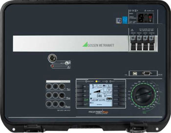
PROFITEST PRIME: State-of-the-Art Test Technology
As the safest test instrument in its product class, the PROFITEST PRIME fulfills all safety criteria for CAT III up to 600 V and CAT IV up to 300 V, and is approved for testing, measuring and monitoring protective measures in the low-voltage ranges of up to 1000 V AC and 1500 V DC in accordance with DIN EN 61557 / VDE 0413.
For the first time, loop measurements for AC/DC sensitive residual current circuit breakers attached to frequency converters for the regulation of electric machines can be conducted as well. The pulse control mode is a further metrological USP, by means of which insulation damage in cable chains can be easily located, for example.
Due to the fact that alone with the PROFITEST PRIME testing is possible in 690 V AC as well as 800 V DC systems, and because voltages of up to 1000 V AC and DC can be measured, a single instrument now suffices for the testing of the electrical safety of photovoltaic systems and wind power turbines, as well as charging stations for electromobility – in addition to control cabinets, machines and industrial systems.
Flexibility is offered in particular by the integrated rechargeable battery, which provides enough energy for the performance of up to 1000 measurements where power is not available from the grid.
IZYTRONIQ: A New Dimension of Test Technology

In order to simplify test sequences and documentation requirements, measured values can be read in to IZYTRONIQ evaluation software from the PROFITEST PRIME by means of push/print via Bluetooth and USB interfaces, and can be combined with measurement results from other devices.
Complete test registers – from the entire system all the way down to the individual measuring points – can be entered via the software in order to define and save test sequences and steps, and to document them in an audit-proof fashion.