Testing the safety of electric machines is one of the essential protective measures used by companies in order to avert danger to life and limb. In addition to electrochemical corrosion and short-circuit current, the most common sources of danger include explosion and fire hazards, the occurrence of dangerous electric arcs and touch current. And thus machines must be carefully tested before initial startup, as well as at regular, periodic intervals and after the completion of any changes or modifications.
LASTINGLY EFFECTIVE PROTECTIVE MEASURES

Before initial startup of an installed electric machine, it’s functional safety must be verified. On the basis of a hazard assessment in accordance with the German ordinance on industrial safety and health (BetrSichV), as well as technical rules for operating safety (in this case TRBS 1201), the exact scope of testing and the respective test types and deadlines, as well as the technical suitability of testing personnel, are determined. Periodic testing of permanently installed machines must be conducted once every four years. Intervals are shortened to as little as six months for portable machines and special types of system segments.
The product standards set forth in DIN EN 60204-1 (VDE 0113-1) for the safety of machines and the electrical equipment of machines serve as a decisive basis for standards-compliant initial testing. They also cover permanently installed machines and are applicable as of the mains connection terminal – or as of the electric outlet in the case of ready-to-plug-in machines.
ASSURING TESTING SAFETY
The assurance of safety during testing enjoys highest priority. For this reason, a mains disconnection device must be provided for each mains connection to one or more machines, as well as for each on-board power supply system, in accordance with EN 60204-1 / VDE 0113-1. Beyond this, suitable devices are also required for disconnecting electrical equipment in order to permit work in the deenergized, electrically isolated state. Finally, the operating equipment must provide reliable protection against electric shock: this applies equally to basic protection against direct contact by means of IP housing protection, insulation, coverings and protection against residual voltage, and to fault protection in the event of indirect contact through the reduction of excessive touch voltage and automatic shutdown of supply power. The selection of a suitable test instrument plays a decisive role in safety, whose measuring category defines the permissible range of applications for the measurement and testing of electrical equipment and systems in low-voltage networks.
KEY TEST SEQUENCES AND MEASUREMENTS
- Testing protective conductor continuity: The resistance of each protective bonding circuit between the PE terminal and relevant points that are part of each protective bonding circuit is measured to this end using a test current within a range of at least 0.2 A and approximately 10 A. Due to the fact that larger currents increase the accuracy of the test results, especially where low resistance values prevail (i.e. larger cross-sectional areas and/or shorter conductor lengths), the PROFITEST PRIME also permits measurements with a test current of 25 A. The test current must be derived from an electrically separated supply source (e.g. SELV, see IEC 60364-4-41, VDE 413.1) having a maximum no-load voltage of 24 V AC or DC. The measured resistance value must be within the expected range according to the length, the cross-section and the material of the related protective bonding conductor. A grounded PELV supply may distort measurement results and must not be used for this reason. This measuring task can be performed in a time-saving fashion with 200 mA and automatic polarity reversal using the PROFITEST PRIME.
- Testing RCDs: Where RCDs are used, their function must be verified in accordance with the manufacturer’s specifications. Test requirements for TN systems correspond to VDE 0100-410 and DIN VDE 0100-600. IEC 60364 (VDE 0100-410) is decisive where TT and IT systems are concerned. Characteristic values for overcurrent protective devices and circuit impedances must be such that if a fault of negligible impedance occurs between a phase conductor and a protective conductor or exposed conductive parts, automatic disconnection of supply power will occur within the specified time.
- Fault loop impedance measurement: A measuring instrument which is compliant with IEC 61557-3 must be used for the measurement of fault loop impedance. The machine to be tested must be connected to supply power with the same frequency as the nominal frequency of the supply power at the intended installation site. If voltage fluctuation occurs within the network during the course of measurement, a valid mean value can be generated on the basis of several measurements. Overall error of ± 30% must be taken into consideration when evaluating the measured values. Due to the fact that measurement is usually performed with the conductor at a temperature of +20 °C, the conductor temperature of +80 °C specified in DIN EN 60909-0 (VDE 0102) must be determined by means of conversion using a correction factor of 1.24. Due to frequency deviations, phase angle control, voltage waveforms and earth fault monitoring, measurement of fault loop impedance is problematic, or even impossible, for machines with frequency converters. In these cases, fault loop impedance measurement should be replaced by careful on-site testing of protective equipotential bonding of the machine and the electric system. Test programs for all relevant measurements of loop impedance without RCD, with type A DC RCD, type B RCD and IΔN/2 (motors) have been installed to the PROFITEST PRIME.
- Insulation resistance tests: During these measurements with 500 V DC between the power circuit conductors and the protective conductor system, insulation resistance may not fall short of a value of 1 M. A lower value of at least 50 kΩ is permissible for certain parts of the electrical equipment, for example busbars, conductor wire or conductor bar systems and slip-ring assemblies. If the electrical equipment of the machine contains surge protection devices which are likely to be triggered during the test, it’s permissible to disconnect them. As an alternative, test voltage can be reduced to a value of less than the voltage protection level of the surge protection devices (but not less than the peak value of the upper limit of the supply voltage). The PROFITEST PRIME is capable of conducting these measurements in steps or with a ramp.
- Voltage tests should be conducted with a test instrument which complies with IEC 61180-2, and the line frequency of the test voltage must be either 50 or 60 Hz. Maximum test voltage must be applied between the power circuit conductors and the protective bonding circuit for a period of approximately 1 s. The maximum value either corresponds to twice the value of rated voltage for the equipment’s supply power or can be fixed at a value of 1000 V. Test requirements are satisfied if no disruptive discharge occurs. Components and devices that are not rated to withstand this test voltage, or have already been voltage tested in accordance with their product standards, are excepted from this requirement.
- Protection against residual voltage: Live parts having a residual voltage greater than 60 V after supply power has been disconnected must be discharged to 60 V or less within a period of 5 s after disconnection of supply power, provided that this rate of discharge does not interfere with proper functioning of the equipment. Components with a stored charge of 60 μC or less are excepted from this requirement. In the case of plugs or similar devices, the withdrawal of which results in the exposure of conductors (for example pins), discharge time to 60 V must not exceed 1 s. Note: Converters and DC busbars typically have a discharge time of longer than 5 s.
- Temperature and atmospheric humidity measurement: Error-free operational reliability of all electric equipment must be verified before, during and after execution of testing at atmospheric temperatures within a range of +5° to +40 °C, and at a relative atmospheric humidity of 50% at a temperature of no more than +40 °C. These measurements can also be performed with the PROFITEST PRIME in an uncomplicated manner by connecting a combined temperature/humidity sensor.
EVALUATION AND DOCUMENTATION
Test documentation prepared in accordance with EN 60204 1/VDE 0113 1 contains information regarding the test laboratory, the inspector and the date of testing, designations of reports for measured values, tested equipment and machines, the measuring and test instruments used to this end and an evaluation of the test results. Visual inspection, the tested circuits, PE measuring points and test results are documented in the test report for initial testing, and the results of the required tests and measurements are recorded for each tested circuit along with the associated protective device.
WHAT WE CAN OFFER YOU:
PROFITEST PRIME: State-of-the-Art Test Technology
As the safest test instrument in its product class, the PROFITEST PRIME fulfills all safety criteria for CAT III up to 600 V and CAT IV up to 300 V, and is approved for testing, measuring and monitoring protective measures in the low-voltage ranges of up to 1000 V AC and 1500 V DC in accordance with DIN EN 61557 / VDE 0413.
For the first time, loop measurements for AC/DC sensitive residual current circuit breakers attached to frequency converters for the regulation of electric machines can be conducted as well. The pulse control mode is a further metrological USP, by means of which insulation damage in cable chains can be easily located, for example.
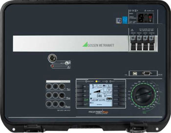
Due to the fact that alone with the PROFITEST PRIME testing is possible in 690 V AC as well as 800 V DC systems, and because voltages of up to 1000 V AC and DC can be measured, a single instrument now suffices for the testing of the electrical safety of photovoltaic systems and wind power turbines, as well as charging stations for electromobility – in addition to control cabinets, machines and industrial systems.
Flexibility is offered in particular by the integrated rechargeable battery, which provides enough energy for the performance of up to 1000 measurements where power is not available from the grid.
IZYTRONIQ: A New Dimension of Test Technology

In order to simplify test sequences and documentation requirements, measured values can be read in to IZYTRONIQ evaluation software from the PROFITEST PRIME by means of push/print via Bluetooth and USB interfaces, and can be combined with measurement results from other devices.
Complete test registers – from the entire system all the way down to the individual measuring points – can be entered via the software in order to define and save test sequences and steps, and to document them in an audit-proof fashion.


