


TESTING EQUIPMENT SAFETY

A broad scope of low-voltage switchgear and controlgear assemblies can be found in industrial, commercial and building management applications ranging from low-voltage main distribution boards, energy distributors and sub-distribution boards, switchgear and control systems, meter and distribution cabinets right on up to construction-site power distribution boards and cable distribution cabinets. In particular where switchgear and control systems for machines, processes and systems are involved, application-specific distribution stations are usually required, so that standardized system solutions are rarely used.
This results in stricter requirements for the electrical installation technician with regard to fabrication and testing of the respective switchgear and controlgear assemblies: he’s responsible for selecting and dimensioning the installed equipment, as well as for internal wiring and connection of the supply lines and cables.
NORMATIVE REQUIREMENTS
The applicable product regulations constitute the legal basis for the equipment of an electrical system. In addition to the general requirements of German public safety law (ProdSG), they also include the requirements set forth in the low voltage directive and, where applicable, the machinery directive. The low voltage directive’s scope of application, which has been in force throughout the EU since April 2016, covers all electrical devices designed for nominal voltages within a range of 50 to 1000 V AC and 75 to 1500 V DC. By means of conformity assessments, technical documentation, operating instructions and safety information, manufacturers and importers of this type of equipment must ensure that no hazards result from the equipment when properly used.
After a transitional period of just over four years, professional planning, installation and testing of low-voltage switchgear and controlgear assemblies has been required to comply with the stipulations set forth in IEC 61439 since November 2014. Distribution systems for rated voltages of up to 1000 V AC and 1500 V DC placed into operation as of this date must be planned and documented in accordance with this standard, if devices from product groups are used whose product standard makes reference to IEC 61439.
EXTENDED MANUFACTURER RESPONSIBILITY
At the same time, manufacturer responsibility was extended when IEC 61439 came into force. Electrical installation companies are now also considered manufacturers. It’s now the responsibility of the qualified electrician to issue his own design verification, in addition to the first piece approval, for all design modifications made by himself which deviate from the type approval issued by the original manufacturer. This certifies the electrical safety of the system for the user. Verification is subdivided into a number of safety-relevant characteristics which have to be validated with individual verifications by means of testing, comparison with a reference design or assessment.
Upon completion or initial start-up of a switchgear and controlgear assembly, the electrician performing the work must prepare a type approval in order to document any material and manufacturing faults, and to verify that the distribution system’s operational reliability is in compliance with the standards. The type approval certifies installation in accordance with the engineering requirements and safe operating performance for the user. In addition to the individual verifications, details concerning the installation company, as well as a type designation or identification number which corresponds to further documentation records, must also be listed to this end.
MEASURING TECHNOLOGY AND TESTING TASKS
Initial testing of a switchgear and controlgear assembly includes visual inspection, as well as testing and measurement. Visual inspection, for example, is used to ascertain compliance with the required housing protection class. Testing of clearance and creepage distances can also be performed in this way, provided that the distances are obviously greater than specified by the standard. In the case of smaller clearances, a surge voltage test must be conducted and physical measurements must be performed in order to verify creepage distances. Visual inspections or testing can be used to check for compliance with assembly instructions and to examine internal circuit connections, in particular screw connections, and to check for correct mechanical functioning of interlocks and actuating elements.
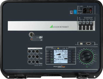
Gossen Metrawatt recommends the PROFITEST PRIME, an especially high-performance test instrument, for metrological testing of electrical protection measures for switchgear and controlgear assemblies. The instrument’s scope of functions covers nearly the entire test spectrum for low-voltage systems up to 1000 V AC / 1500 V DC – ranging from protective conductor testing with 25 A, insulation and loop measurements, testing of all commercially available types of RCDs and insulation monitoring, right on up to the measurement of leakage and touch current, as well as residual voltage. The test instrument’s PRIME AC version is also capable of conducting high-voltage tests up to 2500 V AC, 500 VA. The instrument is protected in accordance with CAT IV and is equipped with special safety technology, so that testing can only be carried out with the help of a key switch, a signal lamp and an emergency off switch, and only when both HV pistols are activated simultaneous. In addition to predefined automatic sequences for rapid execution of various measuring tasks, individualized test sequences can also be programmed.
KEY TEST SEQUENCES AND MEASUREMENTS
- Assurance of protection against electric shock and the short-circuit strength of the distribution system are amongst the most important testing tasks for low-voltage switchgear and controlgear assemblies. All switchgear and controlgear assemblies must be equipped with a protective conductor which disconnects supply power in the event of faults – for example due to defective basic insulation. Protection against the consequences of an internal fault is ensured if the various exposed conductive parts of the switchgear and controlgear assembly are effectively connected to the terminal for the incoming external protective conductor and the resistance of the circuit does not exceed a value 0.1 Ω. A resistance measuring instrument must be used for verification, which conducts an alternating or direct current of at least 10 A for the required test duration from each exposed conductive part inside the switchgear and controlgear assembly to the terminal for the external protective conductor. The PROFITEST PRIME makes it possible to access the individual test steps by means of a rotary switch and to measure the protective conductor’s continuity with current values of up to 25 A.
- All of the switchgear and controlgear assembly’s electrical equipment must be connected when testing insulation properties. The only exceptions to this include devices designed for a lower test voltage in accordance with applicable regulations, as well as current-consuming components such as windings, measuring instruments and surge protection devices which would trigger the flow of current if the test voltage were applied. The power-frequency withstand voltage of the power circuits, and of the auxiliary and control circuits connected to them, is tested. Auxiliary and control circuits which are not connected to a power circuit are tested separately at lower voltage. The utilized test voltage of 1000 to 2700 V AC depends on the rated insulation voltage of the tested circuit and may not exceed 50% of the full test value at the moment of application. After the maximum value has been reached, test voltage is maintained for 60 (+2) seconds. Due to the fact that testing with alternating voltage results in a higher test severity, direct voltage testing should only be conducted if, for example, filters or capacitors prevent measurement with alternating voltage. Corresponding sequences can be stored to the PROFITEST PRIME AC for these test procedures as well.
- A further test task involves warm-up verification. It verifies that operating temperatures don’t result in any functional impairment or premature ageing of the switchgear and controlgear assembly, and that excessive heat is not dissipated to the external conductors. A combined temperature/humidity sensor is connected to the test instrument in order to perform measurements with the PROFITEST PRIME, and the stored test program is started. Both before and after testing, ambient temperature and relative humidity must remain within specified limits.
- Finally, testing protective measures at switchgear and controlgear assemblies includes standards-compliant leakage current measurement, i.e. protective conductor current in accordance with VDE 0701-0702, as well as touch current at exposed conductive parts which are not connected to the protective conductor in accordance with VDE 0701-0702. Insulated housings, handles and conductors must also be tested during the course of this procedure. Various measuring methods are made available by the PROFITEST PRIME for these testing tasks. Protective conductor current can be measured by means of direct measurement with two measuring probes and an internal measuring shunt, or with an external current clamp plus filter directly via the protective conductor. Alternatively, differential measurement via active conductors L-N using an external current clamp is also possible. Measurement of touch current is conducted with two measuring probes and an internal measuring shunt.
WHAT WE CAN OFFER YOU:
PROFITEST PRIME: State-of-the-Art Test Technology
As the safest test instrument in its product class, the PROFITEST PRIME fulfills all safety criteria for CAT III up to 600 V and CAT IV up to 300 V, and is approved for testing, measuring and monitoring protective measures in the low-voltage ranges of up to 1000 V AC and 1500 V DC in accordance with DIN EN 61557 / VDE 0413.
For the first time, loop measurements for AC/DC sensitive residual current circuit breakers attached to frequency converters for the regulation of electric machines can be conducted as well. The pulse control mode is a further metrological USP, by means of which insulation damage in cable chains can be easily located, for example.
Due to the fact that alone with the PROFITEST PRIME testing is possible in 690 V AC as well as 800 V DC systems, and because voltages of up to 1000 V AC and DC can be measured, a single instrument now suffices for the testing of the electrical safety of photovoltaic systems and wind power turbines, as well as charging stations for electromobility – in addition to control cabinets, machines and industrial systems.
Flexibility is offered in particular by the integrated rechargeable battery, which provides enough energy for the performance of up to 1000 measurements where power is not available from the grid.
IZYTRONIQ: A New Dimension of Test Technology

In order to simplify test sequences and documentation requirements, measured values can be read in to IZYTRONIQ evaluation software from the PROFITEST PRIME by means of push/print via Bluetooth and USB interfaces, and can be combined with measurement results from other devices.
Complete test registers – from the entire system all the way down to the individual measuring points – can be entered via the software in order to define and save test sequences and steps, and to document them in an audit-proof fashion.