


THE USE OF UNDERGROUND CABLES
An underground cable is an electric line laid in the ground with particularly durable insulation on the outside, i.e. the cable sheath, which prevents its destruction due to chemical influences in the soil or small animals (rodents) living in the ground.
Underground cables have several advantages in comparison to overhead lines. They’re protected against damage – including weathering – and they don’t visually disrupt the landscape. Disadvantages include higher maintenance costs and greater difficulty in localizing faults, such as those caused by construction work and unintentional damage to cables laid underground. The higher costs associated with these factors are disadvantageous in power engineering applications in the high-voltage range.
In the telecommunications sector, local connection cables are pressurized to a level of 10 mbar. As a result of this overpressure, air is blown against any infiltrating moisture in the event of minor leaks in the cable sheath, so that no moisture can penetrate. In the event of a pressure drop, a sensor indicates that air is escaping from the system. The cable is then pumped up with a special gas, making it possible to pinpoint the leak with the help of detection equipment.
FAULT SOURCE DETECTION
The goal of fault source detection is to identify broken or pinched cables and pinpoint fault location. The properties of time domain reflectometry are taken advantage of to this end, in order to detect any changes which take place within the medium. TDR can be used to localize the end of the cable, a cable break or a short-circuit between the inner and outer conductors.
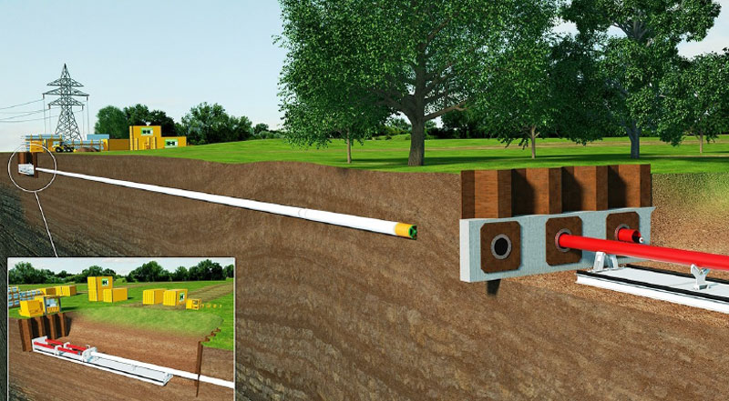
Underground Cable Laying with E-Power Pipe® Graphic: Herrenknecht AG
TDR / TIME DOMAIN REFLECTOMETRY
The so-called TDR measurement is one possible option for examining cables. TDR stands for time domain reflectometry which can be used to ascertain cable lengths, and to detect cable faults, cable breaks, short-circuits and pinched cables.
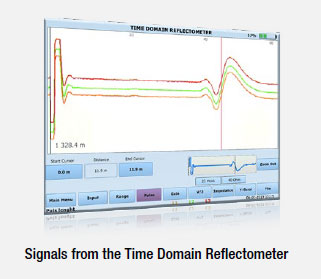
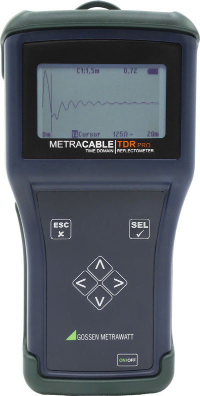
A TDR measuring instrument, for example the METRACABLE TDR, emits an electrical pulse and then calculates cable lengths or fault locations based on how much time elapses before the pulse returns to the transmitter. A wide variety of faults can also be identified by analyzing the various waveforms.
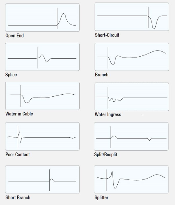
By means of the TDR method, the instrument transmits a pulse to the cable which is reflected by cable faults and then returns to the instrument. The type of fault can be determined on the basis of characteristic reflection curves.
A TDR measuring instrument is a powerful tool for checking symmetrical lines. In addition to determining cable length, the displayed reflection curves can also be used to identify and pinpoint cable faults. This saves time during troubleshooting and avoids unnecessary work.
With the aid of a step function generator, a sloping signal is generated at one end of the cable. The signal edge is propagated through the medium and is reflected when it reaches the other end, or by faults within the cable. With the help of a suitable evaluation circuit or an oscilloscope, the transmitted signal is then compared with its reflection and information about the reflection’s transit time and amplitude, as well as its capacitive, resistive and inductive characteristics, are determined. The simple view of the reflections in the oscilloscope makes it possible for the observer to assess their characteristics, even without in-depth technical knowledge.
CABLE TYPE
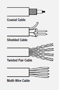
Cables have various electrical properties which influence length measurement. In order to ensure that length measurement is as accurate as possible, care must be taken to use the correct velocity of propagation value (VP value). The more accurate this value is, the more precisely cable length will be displayed. Cable databases integrated into test instruments like the METRACABLE TDR include various cable types, along with the cable characteristics which are relevant for length measurement. Symmetrical cables are supported (see figure for examples). Exactly which options a TDR offers is described in the sections below.
A suitable cable fault detector can examine a broad range of different cable types using the TDR method, and pinpoint possible fault locations. The METRACBLE TDR is capable of examining cables with lengths of up to 15 kilometers.
LENGTH MEASUREMENT
Measuring the length of cables in the electrical industry was one of the first applications for time domain reflectometry. TDR is used to measure the time it takes for an emitted pulse to return to the instrument after reflection. If the cable’s velocity of propagation is known, which depends on cable insulation, measured time can be used to directly infer cable length. The term cable radar has evolved from this application.
Whereas oscilloscopes were required for these measurements in the past, ready-made measuring instruments are now available which display the length value directly. This method is widely used in the fields of telecommunications and network technology. When new cabling is laid in buildings, the installed network cable is billed according to measured values based on time domain reflectometry.
FAULT SOURCE DETECTION
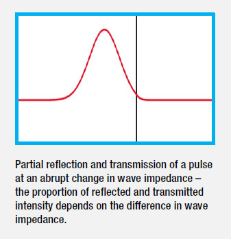
The goal of fault source detection is, for example, to identify broken or pinched underground cables and to pinpoint the location of the respective fault. The properties of time domain reflectometry are taken advantage of to this end – in order to detect not only total reflection, but rather every change in the medium as well. Total reflection only occurs at the end of the cable, at a cable break or at a short-circuit between the inner and outer conductors. As long as the pulse is propagated along an unaltered medium, wave impedance in the cable doesn’t change. However, if the pulse wave encounters a pinch, impedance changes and partial reflection occurs. The location and extent of the pinching can then be inferred from the time of arrival of the reflection and its nature.
PULSE WIDTH AND PULSE DURATION
Pulse width or pulse duration also influences the measurement. Smaller pulse durations have a much better resolution, i.e. they can be used to locate faults which are close together. As a disadvantage, greater lengths can no longer be measured since – due to attenuation resulting from the long cable – the reflection of the short pulse is too small to permit measurement. This relationship is reversed for larger pulse widths. Longer cables can be measured but some of the faults might not be displayed. This may make it necessary to perform several measurements.
In order to be able to work with optimum resolution for each cable type and length, pulse width is adjustable at the METRACABLE TDR.
TYPICAL CABLE FAULTS AND THEIR WAVEFORMS