


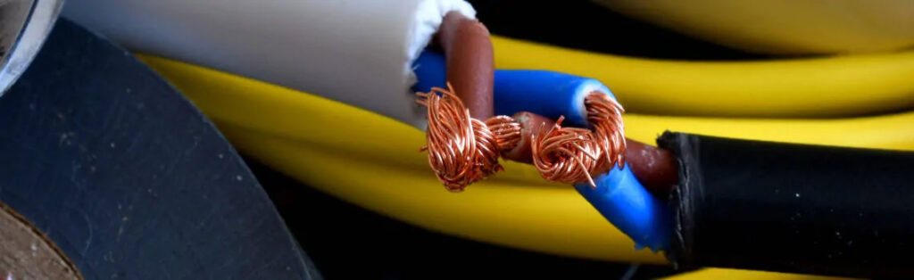
Existing copper cables can be used for the expansion of an existing communication structure. The alternative to this is completely new cabling.
This raises the following questions:
How can an existing line be checked? Where are possible faults located?
1 How does a TDR meter basically work?
One way to check lines is the so called TDR measurement. TDR stands for Time Domain Reflectometry and is used to determine cable lengths, cable faults, cable breaks, short circuits and cable crushes.
A TDR meter, such as our KE2100, sends an electrical pulse and then calculates the cable lengths or fault location based on the time taken to return to the transmitter.
1.1 How does a TDR measurement work?
In the TDR method, the device sends a pulse to the cable, which is then reflected by cable faults and sent back to the device. The type of fault can be identified by characteristic reflection curves. The measurement device also indicates the location of the fault to an accuracy of approximately 0.3 m.
1.2 Why can the time between pulses be adjusted?
The pulse width or pulse duration has an influence on the measurement. Smaller pulse times have a much better resolution, i.e. errors that follow each other closely can be displayed better. The disadvantage is that longer lengths cannot be measured accurately. With larger pulse widths the process is reversed. This means that longer cables can be measured, but possibly not all errors can be displayed. Therefore it may be necessary to take several measurements.
This is one reason why different pulse widths are adjustable on our KE2100.
2 What kind of measurements can be performed with a TDR?
A suitable cable fault measuring instrument, such as our KE2100, can use the TDR method to test a wide range of different cables and determine the possible fault location. The KE2100 can even inspect cables up to 15 kilometers long. Consequently, some of the supported cable types are shown. The possibilities a TDR offers is shown in the following figure:
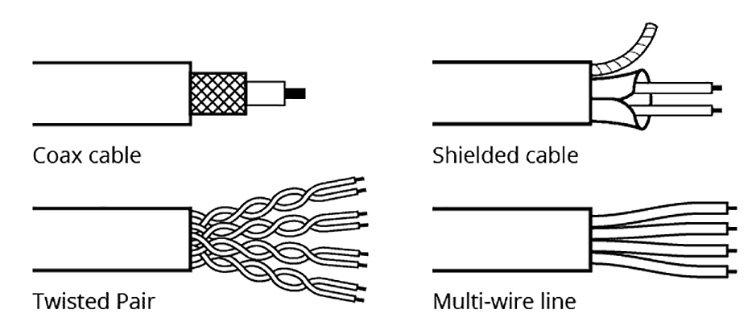
Fig. 1: Cable types supported by TDR
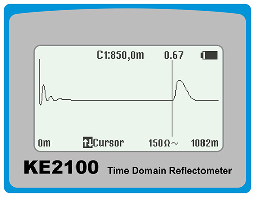
Fig. 2: Cable length measurement with TDR
2.1 How does the length measurement work?
In a length measurement, an electrical impulse is fed in at the beginning of the cable. This impulse passes through the cable section until it is reflected at the open cable end and returns to the beginning of the cable and the measuring device. The time difference between transmission and arrival is measured. This time is then converted into a length measurement using the cable parameters and pulse settings.
2.2 How can causes of faults be found? What do the faults look like?
With the TDR method, the device sends a pulse onto the cable, which is then reflected by cable faults and sent back to the device. The type of fault can be identified by characteristic reflection curves. The instrument also indicates the location of the fault to an accuracy of approximately 0.3 m. Some typical reflection curves and the associated cable faults are shown in the figure below:
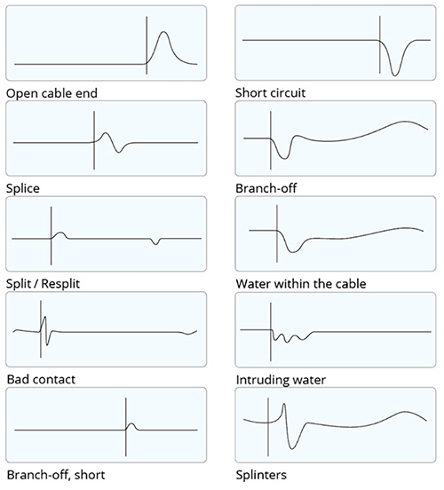
Fig.3: Typical TDR curves
2.3 Why do the cable parameters have to be set?
Cables have different electrical properties which affect the length measurement. To ensure that the length measurement is as accurate as possible, the correct value of the propagation velocity (VF value) must be observed. The more precise this value is, the more accurately the cable length is displayed. The cable database of our KE2100 contains different types of cables with the corresponding values.
Summary
A TDR measurement and a TDR meter are a powerful tool for checking lines. In addition to determining the cable length, cable faults can also be determined and detected by displaying the reflection curves. This saves time during troubleshooting and avoids unnecessary work.