


Both privately and within a company, the networking of computers and peripherals is an important component. Ideally, communication must be possible at all times. In the event of faulty communication, quick help is often necessary.
A network tester provides information about the condition of the network and its cabling. But how does a network tester work? Which cable faults can be detected? What additional measurements are possible?
1 How does a network tester basically work?
Network testers are devices that can be used to check network cables and network connections in the Ethernet. At the beginning of this blog post, we will take a closer look at how a network tester works, which cables can be checked and how the measurement results are presented.
1.1 Which cables can be tested with a network tester?
The installed communication and signal lines can be installed in different topologies and based on different cables. Probably the most commonly used network cables are 8-wire, originally largely unshielded and nowadays shielded. As a rule, a RJ45 plug or a RJ45 socket is used to connect the network line. A network tester is used at this transfer point and checks the desired network line. However, the possibility of checking should not stop there. Telecommunication cables of telephone systems can also be 4-wire and use an RJ11/RJ12 plug.
A good network tester should also offer the option of testing. Some devices can additionally test coax cables for continuity.
Most network testers (e.g. KE7200 from Kurth Electronic) use an integrated cable database in which various cable variants are stored and the user can configure individual wiring. The cable to be tested is then directly tested for its specific wiring by using the cable database.
1.2 How does a network tester work?
Network testers usually work with two devices, i.e. with a transmitter and a receiver. After setting the cable type, the transmitter sends a signal to the receiver, to which the receiver responds. The transmitter sends specific signal sequences over the respective wires. The receiver checks and indicates to the transmitter whether the signal sequences have arrived correctly. If the signal sequences between the transmitter and receiver do not match the expected signal sequence, the network tester uses the signals that were not received or received incorrectly to interpret which errors are present in the cabling.
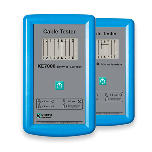
Transmitters and receivers for network testers come in different designs and construction forms. There are network testers that work with two equivalent main devices. With this variant, the pair of devices decides after connection who is the transmitter or receiver and then tests the cable. The test results can thus be displayed on both devices. For a new measurement, however, both devices must be reconnected. Such a device pair is the KE7000 from Kurth Electronic.
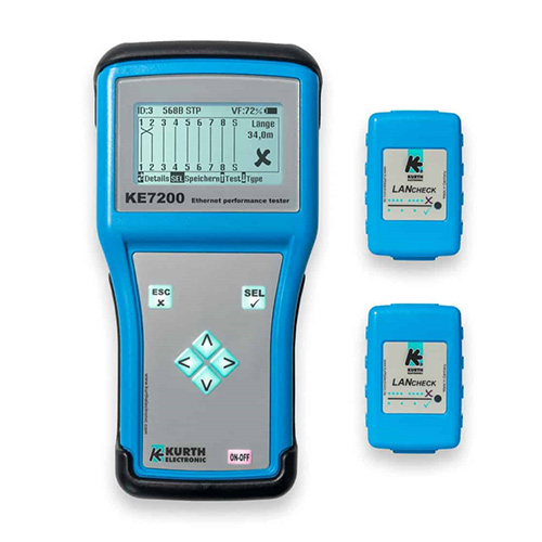
Another variant is the combination of a measuring device and the so-called remote units. In this case, the signal of the measuring device is sent back to the transmitter via a passive circuit of the remote, where it is then analysed. The result is only displayed on the measuring device. The use of remote units, however, offers the decisive advantage that a large number of them can be plugged into a junction, for example. The measuring device is then only used to scan the individual ports. The series of measurements can thus be carried out more quickly. In addition, passive remotes do not require an additional power supply.
With network testers, such as the KE7100 and KE7200 from Kurth Electronic, several remote units can be distributed and tested in different network sockets, which saves time and walking distances and thus the measurement time is drastically reduced. Up to 32 remote units can be connected and managed on the KE7100 and KE7200.
1.3 How are the results presented here?
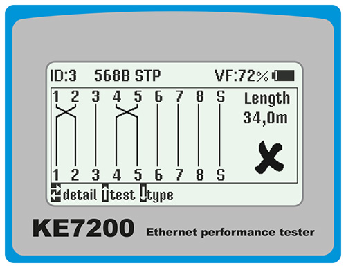
Fig. 3: Wiremap with intercharge of wires 1 and 2
The display of the measurement results varies depending on the network tester and network tester class. With very simple network testers or cabling testers, the result is often displayed with flashing and illuminated LEDs. Here, each wire is assigned an LED, which then indicates the possible error by visual adaptations. The readability of LED displays is often difficult.
The use of a display with a wiremap makes the interpretation of the error much easier for the user. If, for example, two wires have been swapped, this can be quickly recognised and thus corrected (see Fig. 3).
In addition, further information can also be shown within a display, such as the cable type or the cable length. Network testers with TDR function can even display the distance to the fault in the event of a short circuit or interruption. To do this, the network tester sends an electrical pulse onto the cable, which is reflected by kinks, breaks and other damage in the cable. The reflected signal is analysed by the network tester, which allows conclusions to be drawn about the type and location of the fault. This offers an important advantage in the subsequent repair.
With some network testers, the measurement results can also be saved and printed out in a protocol.
2 Which cable faults can be detected?
After taking a closer look at how network testers fundamentally work, attention is now turned to the area of application. In the following chapter, the cable faults that can be displayed are listed and described where applicable.
2.1 Which wiring errors are displayed?
When using a network tester, the wires and wire pairs of the cable sections are checked for continuity, interruption, short circuit, interchange, overdraft (split pair) and also bridge tap and then shown in the display. When choosing a network tester, the scope of the cabling faults that can be displayed is decisive: The more possible faults that can be displayed, the fewer faults will be overlooked in case of doubt. Split pair errors and bridge tap errors are often not displayed on simple devices.
2.2 What is a Bridge Tab and what does Split Pair mean?
A bridge tab, also referred to as bridged tap, is where a line is branched without signals being directed in a specific direction via a circuit. These have long been used in domestic installations to distribute telephone lines. This allowed a telephone line to be distributed to several rooms. With today’s DSL connections, these bridge tabs can lead to interference or even a total loss of internet service, as signals are reflected by bridge taps and thus generate interference signals.
In the case of a split pair, the combination of a pair of wires is reversed and thus the twisting is overridden. Simple cabling testers cannot display this error and show the line as error-free. However, without the usable twisting, which reduces the so-called crosstalk (electromagnetic interference of parallel lines), mutual interference of the signals can occur. In the case of a split pair, for example, wires 2 and 3 can be interchanged on both sides. This means that the non-twisted wires 1-3 as well as the wires 2-4 would form a pair and negatively influence each other due to the increased crosstalk.
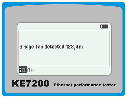
Fig. 4: Bridge tap detection with the KE7200
2.3 How can the fault be localised?
Faults, such as Bridge Tab, can be localised with a TDR length measurement. The distance to the branch is then displayed. In the example measurement with the “KE7200”, this is 128.4 m. More detailed information on fault localisation using TDR can be found in our blog post “What is a TDR measurement?“.
3 Which measurements are additionally useful?
Independent of cable fault measurements, modern network testers can also perform other tests. These include Power over Ethernet (PoE) measurement, the port finder function in active networks or a ping stress test, as well as the creation of a handover protocol.
3.1 How can PoE++ be measured?
If the load capacity of the port is to be checked, a PoE test must be carried out and the available power of the port determined. On the one hand, this indicates whether the power of a modern switch has been reduced by the software or whether the total power of the switch is sufficient to supply several PoE devices at once with sufficient power. With PoE++, a power of up to 90 watts is possible.
| PoE (802.3af-2003) | 36 – 57 V DC | 14,5 W |
| PoE+ (802.3at-2009) | 42,5 – 57 V DC | 30 W |
| PoE++ (4-paar PoE, 802.3bt-2018) | 42,5 – 57 V DC | 90 W |
Table 1: Maximum performance of PoE standards
Compared to most other devices, the network testers from Kurth Electronic offer the decisive advantage that they do not only query the theoretically available power at the switch, but measure the actual incoming power. This ensures that the result is not distorted by several connected PoE devices or by the power attenuation of long cables.
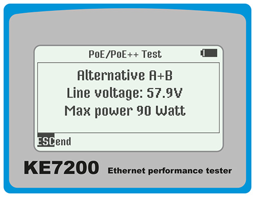
Fig. 5: PoE test with the KE7200
3.2 Is active logging into the network possible?
Sometimes it is necessary to examine active networks that cannot be switched off for troubleshooting, e.g. because they serve critical infrastructure. It can also be helpful to get an overview of active network participants and to check the transmission rates in the network. This is where a network tester that can also examine an active network comes in handy.
With the KE7200 it is also possible to connect to an active network. Here you can select in the menu whether the dial-in is to take place via DHCP or static IP address. The active dial-in into the network enables further test possibilities of the network tester. Active network tests, such as the detection of link speed in 10/100/1000 Mbit networks, the listing of existing network participants incl. name, IP and MAC address of the participant as well as the configurable ping stress test with detailed statistics provide information about the network and possibly faulty components.
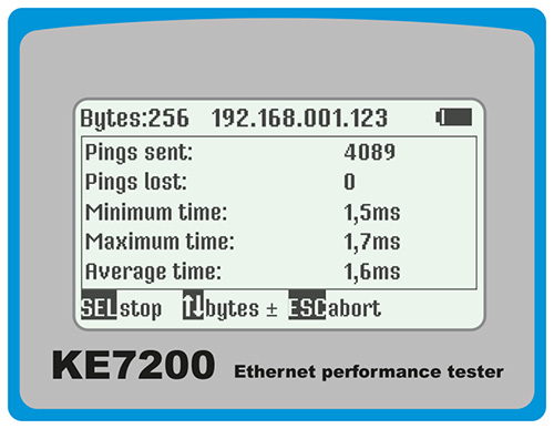
Fig. 6: Ping stress test with the KE7200
Summary
Network testers have continued to evolve. Checking the cabling is now standard. Modern network testers also offer the option of measuring split pairs and bridge taps, for example. It is possible to actively connect to the network and carry out a load test on the PoE socket. The measurement is rounded off by the storage and subsequent logging of the measurement results for handover to the customer.