


The German telecommunications network was built up over decades using wire pairs made of copper. This network structure first enabled analogue communication and later digital communication.
The desired communication possibilities are becoming ever greater, as is the necessary data bandwidth. The current copper network has reached its limits.
1 How does a fibre optic cable work?
Fibre optic cables transmit information not via the use of electric current, as is common in copper cable, but optically, meaning via light.
Fibre optic cables have numerous advantages over copper cables, for example they are able to transmit significantly higher bandwidths and at the same time bridge very long distances. Compared to copper cables, fibre optic cables have only low signal attenuation and signal loss. Another important advantage is their insensitivity to electromagnetic fields.
Fibre optic lines are already the most important component of modern telecommunication and data networks and are replacing the classic copper lines due to their many advantages. But why is this so? In order to work through these topics, we will start by looking together at how a fibre optic cable is constructed.
1.1 How is a fibre optic cable constructed?
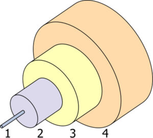
Fig. 1: Schematic structure of a fibre optic cable
Illustration by Bob Mellish edited by Benchill under the CC BY-SA 3.0 licence
Figure 1 shows the structure of a fibre optic cable or optical fibre schematically. In the centre at number 1 is the core. It is surrounded by a sheath. The sheath at number 2 plays an important role in signal transmission in conjunction with the core. The cladding is constructed in such a way that it has a lower refractive index in relation to the core. By reducing the refractive index in the cladding, the signal from the core is reflected at the so-called boundary layer. This total reflection causes the signal to be guided on the core.

Fig. 2: Schematic light guidance
The buffer 3 and the jacket 4 both serve to actually protect the conductor. The interaction of the two protective layers is intended to dampen mechanical stresses but also to prevent natural influences such as moisture ingress.
1.2 What does singlemode mean?
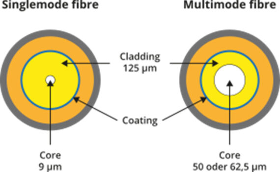
Fig. 3: Difference singlemode to multimode
Singlemode glass fibres have a core diameter of 9 µm, as can also be observed in Figure 3. The thickness of the cladding glass is 125 µm. The small core diameter keeps the number of reflections low, as in figure 2. This approach reduces the attenuation of the fibre optic cable and thus leads to further and also faster signal transmission.
However, the thin core diameter also brings a disadvantage. Only one signal source can be sent over the fibre.
Due to the low attenuation and fast signal transmission, singlemode fibres are mainly used to bridge long cable runs.
1.3 How does a multimode cable work?
The diameter of the core of a multimode fibre is 50 µm to 62.5 µm. It is thus many times larger than the core of a singlemode fibre of 9 µm. The relationship can be seen schematically in Figure 3. The larger core diameter enables the multimode fibre to transmit several signal sources in parallel via the core. The use of multiple signal sources increases the amount of data that can be transmitted. At the same time, the number of reflections in the fibre optic cable increases, which increases the attenuation. Multimode fibres are used to transmit large amounts of data over short distances.
1.4 What is the difference between the gradient index and the step index?
Figure 4 shows the different multimode fibre types compared to singlemode with only one fibre type. Multimode fibre cores have either a graded index or a step index, with graded index fibres being more common. This index describes the type of path that the modes (light) take when transmitting through the fibre core.
In step index multimode fibres, the refractive index is the same across the entire cross-section in the core of the conductor and one step lower in the cladding glass. However, the transmitted light can propagate in hundreds of modes in it, which leads to a dispersion of the propagation time. This so-called mode dispersion is counteracted with gradient index fibres, because these reduce the mode dispersion. The course of the modes through a graded index fibre is thus not in “jags” as with a step index fibre, but on harmonically curved paths. The advantages are noticeable in higher data transmission rates and greater ranges.
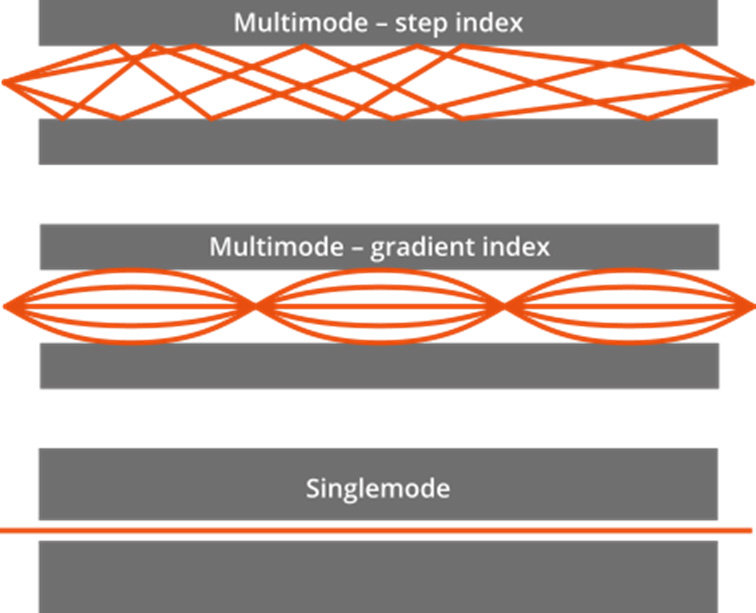
Fig. 4: Multimode step index vs. Multimode gradient index vs. Singlemode
2 What types of fibres are there?
Similar to the cable categories (Cat) for network cables based on copper, there are classes or categories for singlemode and multimode fibre optic cables. The grouping into categories enables a direct conclusion to be drawn about the possible transmission quantity of the data and range. In the following section we provide a more detailed overview of the respective fibre optic categories.
2.1 Which fibre classes are available in the singlemode range and which transmission speeds are realised?
Singlemode fibres are divided into two categories, the so-called OS1 and OS2. OS1 fibres have a higher attenuation compared to OS2 fibres. The transmission range is therefore higher with OS2 because of the lower attenuation. However, the definition of the categories is not about the actual cable parameters but about the type of construction.
OS1 cables are designed for indoor use. The construction is referred to as tight buffered cables. These have an attenuation of 1 dB/km and are thus suitable for distances of 10 km. OS2 cables are designed for outdoor installation.
OS2 cables are referred to as loose tube cables. Their attenuation is 0.4 dB/km. These are suitable for blowing in during road construction, for example. They can also be used to bridge distances of up to 200 km, which makes them suitable for use in long-distance networks. The cable category standards are defined in ITU-T G652x. Singlemode fibres are usually supplied with yellow sheathing, regardless of the category.
| Attenuation | 1 dB/km | 0,4 dB/km |
| Range | 10 km | 200 km |
| Structure | Buffered cable | Loose tube cable |
| Standard | ITU-T G652A/B/C/D | ITU-T G652C/D |
| Area of application | Outdoors | Indoors |
| Cable colour | Yellow | Yellow |
Table 1: Singlemode OS classes
The possible transmission speed and transmission length depends on the wavelength used and the type of fibre optic cable. The wavelengths most commonly used for singlemode fibres are 𝛌 = 1310 nm and 𝛌 = 1550 nm or 𝛌 = 1490 nm. These correspond to the O, C and S bands respectively.
| 1 Gbit/s | 1000BASE-LX10 | 1310 | 10 km |
| 1000BASE-EX | 1310 | 40 km | |
| 1000BASE-ZX | 1550 | 80 km | |
| 10 Gbit/s | 10GBASE-LR | 1310 | 10 km |
| 10GBASE-ER | 1550 | 40 km | |
| 40 Gbit/s | 40GBASE-LR4 | 1310 | 10 km |
| 40GBASE-ER4 | 1550 | 40 km |
Table 2: Excerpt of fibre optic cable types and range
Table 2 compares various types of fibre optic cables. The cable type indicates which wavelength can be used. When comparing the wavelengths 1310 nm and 1550 nm, it is noticeable that the transmission length is higher when using 1550 nm.
2.2 What classes and speeds are available with multimode?
Multimode cables are currently classified in five classes, OM1 to OM5. OM stands for “Optical Multimode”. The attenuation of the cables is the same for the different cable types and depends on the wavelength. The OM classes indicate the amount of data for which the respective fibre optic cable is suitable. As the number increases, so does the amount of data. The most common wavelengths for multimode fibres are 𝛌 = 850 nm, 𝛌 = 1300 nm or also 𝛌 = 953nm.
| OM1 | Orange | 3.5 dB/km | 1.5 dB/km |
| OM2 | Orange | 3.5 dB/km | 1.5 dB/km |
| OM3 | Aqua | 3.5 dB/km | 1.5 dB/km |
| OM4 | Violet | 3.5 dB/km | 1.5 dB/km |
| OM5 | Lime | 3.5 dB/km | 1.5 дdB/km |
Table 3: OM Cable types
Typically, the light sources for OM1 and OM2 fibre optic cables are LEDs, whereas OM3 and OM4 fibre optic cables use more efficient lasers. OM3 and OM4 fibre optic cables are only used at 850 nm. By using so-called VCSE lasers, a larger amount of data can be transmitted over a greater distance via OM3 and OM4 cores.
| 1 GBit/s | 300 m | 500 m | 1000 m | 1000 m | – |
| 10 GBit/s | 30 m | 80 m | 300 m | 500 m | – |
| 40 GBit/s | – | – | 100 m | 125 m | – |
| 100 GBit/s | – | – | 70 m | 100 m | 150 m |
Table 4: Excerpt of transmission lengths according to OM category
3 How to lay a fibre optic cable?
A fibre optic cable or fibre optic “optical waveguide” has a low attenuation compared to a copper cable and thus enables the bridging of greater distances. Proper installation plays an important role in maintaining the low attenuation. Damage to the cable due to improper mechanical stress will worsen the attenuation or, in the worst case, break the connection. It is also important to keep the fibre (ends) clean, dust-free and free of moisture etc. at all times. What must be observed during installation to avoid possible damage and loss is explained in the following paragraphs.
3.1 Which bending radius must be observed?
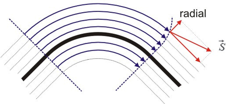
At the beginning of the blog post, it became clear that the movement of the signal depends on the core and its cladding. The total reflection at the boundary layer causes the signal to be conducted. When laying or installing a fibre optic cable, bending cannot be avoided in some places. The bending of the cable causes the distance between the core and the boundary layer to increase on the outside of the bend, thus extending the path length. This lengthening then causes an increase in the damping values.
If the bend is too strong, the so-called limiting angle of the total reflection could be exceeded. If the limit angle is exceeded, reflection is no longer possible or only partially possible. As a result, parts of the signal leak out of the core. Depending on the degree of damage and deterioration of the attenuation, the bending can lead to a complete failure of the fibre optic cable. The acceptable bending radius depends on the glass fibre used.
3.2 What losses can occur during installation?
When laying a fibre optic cable indoors, excessive bending radii cause the attenuation to increase. As a rule, however, a fibre optic line is not only used inside a building, but also to connect the building to the network structure, as we explain in our post about the structure of the fibre optic network.
Each connection or link can lead to insertion or coupling losses. These can occur, for example, during splicing itself, or if the respective types of fibre do not match. One difference could be the phase cut of the core in the case of the cables used. The diameter of the cores to be connected should be the same. Losses add up and can completely interrupt signal transmission. It is advisable to check the fibre optic path after installation using suitable measurement technology and to clean the cabling with suitable cleaning tools at every plugging cycle.
Summary
This blog post explained how a fibre optic cable works. It also showed all the different types of fibre. Last but not least, it described in detail how a fibre optic cable is laid.