


In this guide, we introduce you to different measurement methods for testing cables – both network cables or general twisted pair cables – which enable you to locate cable faults in a more reliable way. Frequently, when either network errors or a poor network performance occur, attempts are made to fix those issues at software level. But the cause regularly lays in the wiring of the ICT (Information and Communication Technology) installation itself. For example, a computer keyboard is obviously not suitable for hammering a nail into a wall. The same holds true for a DHCP reset in terms of identifying a twisting error in the patch field. For this purpose special measuring procedures and measuring tools (line finders, network cable testers, (fault) locating devices) exist which have been specially developed for analysing and localising cable faults.
First, we will review the structure of cable types usually used in a network (e.g. LAN cable, telephone cable, twisted pair cable) in order to then be in the position to present you the matching measurement methods (continuity test, wiremap, fault location) as well as the special features of each measurement method.
1 Different cable types in the CT network
In the telecommunication network (ICT network) people nowadays almost only use twisted pair cables or fibre optic cables. So these cables have nearly completely replaced Coaxial cables, which were also used in the past. As already mentioned, this blog post is about copper installations, i.e. about telephone cables and Ethernet cables (patch cables) and thus ultimately about twisted pair cables.
1.1 The twisted pair cable
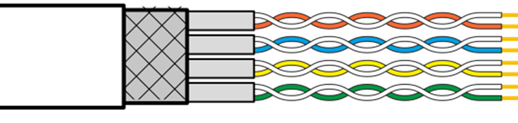
Fig. 1.1: Structure of a twisted pair cable
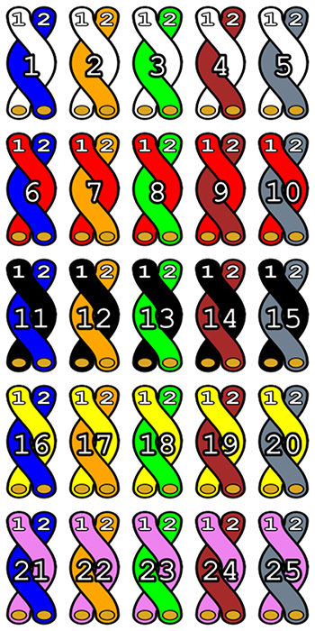
Fig. 1.2: Colour coding of a twisted pair cable (25 wire pairs)
Illustration by Rafał Pocztarski, edited by Pumbaa80, under the GNU General Public License.
Twisted pair cables (invented in 1881 by Alexander Graham Bell) are cables in which the individual wire pairs are twisted in order to improve electromagnetic properties. In direct comparison with a single wire or an untwisted, symmetrical pair of wires, a twisted pair cable has less crosstalk between adjacent pairs of wires, less electromagnetic interference and is also more robust (more immune) against electromagnetic interference. In installation cables and LAN cables you use twisting. The individual wire pairs are colour-coded as shown in Figure 1.2. The colours per column and per row are stable. This means for example that in column one a wire is always blue (see wire pair 1, 6, 11, 16, 21) and in row one a wire is always white (see wire pair 1, 2, 3, 4, 5).
Installation and patch cables, or more generally twisted pair cables, often have a shield to prevent electromagnetic interference. On one side single wire pairs can have a shield, but also several wire pairs can have a common shield and/or the entire cable. In ISO:IEC 11801:2002 (Annex E) an international standard is defined to bring the various shielding methods together. For this purpose three letters and a corresponding format XX/YZZ got introduced. This identification number is printed on each shielding sheath and therefore each twisted pair cable is uniquely identifiable. The ID is composed as follows:
- XX for the overall shielding:
- U = unshielded
- F = foiled
- S = screened
- SF = foiled and screened
- Y stands for the wire pair shielding:
- U = unshielded
- F = foiled
- S = screened
- ZZ stands for:
- TP = Twisted Pair
- QP = Quad Pair
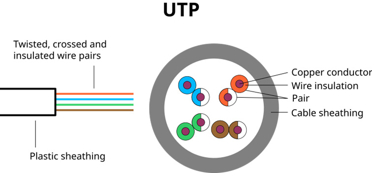
Fig. 1.3: Scheme of an UTP cable
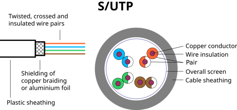
Fig. 1.4: Scheme of a S/UTP cable
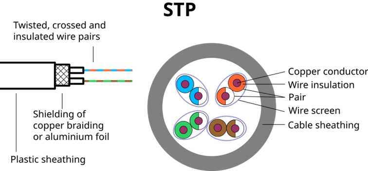
Fig. 1.5: Scheme of a STP cable
1.3-1.5: Based on an illustration by Uwe Schöbel edited by Svgalbertian, under the GNU Free Documentation License.
| UTP, TP | U/UTP | None | None |
| STP, ScTP, PiMF | U/FTP | None | Foil |
| FTP, STP, ScTP | F/UTP | Foil | None |
| STP, ScTP | S/UTP | Braiding | None |
| SFTP, S-FTP, STP | SF/UTP | Braiding and Foil | None |
| FFTP, STP | F/FTP | Foil | Foil |
| SSTP, SFTP, STP, STP PiMF | S/FTP | Braiding | Foil |
| SFSTP, SFTP, STP | SF/SFTP | Braiding and Foil | None |
Overview of cable types
1.2 Cable categories
Over time, transmission speeds and bandwidth requirements have increased dramatically. While a few kHz (kbit/s) were still sufficient for a telephone call in the past, today’s media consumption requires several MHz (MBit/s) to receive Netflix streams, for example. The biggest processor, the best graphics card or the fastest DSL connection is of no use if the bottleneck is the cable itself. As can be seen in Table 1.7, there are now eight cable categories (Cat 1 – Cat 8) that support different bandwidths and thus ultimately different transmission speeds.
| Cat 1 | UTP | 0.4 MHz | Telephony cables |
| Cat 2 | UTP | 4 MHz | ISDN |
| Cat 3 | UTP | 16 MHz | 10BASE-T and 100BASE-T4 |
| Cat 4 | UTP | 20 MHz | Token Ring with 16 Mbit/s |
| Cat 5 | UTP | 100 MHz | 100BASE-TX and 1000BASE-T |
| Cat 6 | UTP or STP | 250 – 500 MHz | 1000BASE-T, 10GBASE-T |
| Cat 7 | S/FTP | 600 – 1000 MHz | 10GBASE-T |
| Cat 8 | S/FTP | 1600 – 2000 MHz | 40GBASE-T and 100GBASE-T |
Properties of Cat 1 – Cat 8 twisted pair cables
One more small note: Each cable has got attenuation, i.e. the signal is attenuated and the signal strength decreases. The higher the frequency, the greater the attenuation. The latter is not constant and depends on frequency. I.e. signals at 1 kHz are attenuated less than signals at 1 GHz. The longer the cable, the longer the signal was exposed to the attenuation and the lower is the resulting signal strength.
If, for example (calculation example), the attenuation at 1 kHz is 0.1 dB per meter and the signal strenght at the beginning of the line is 10 dB, this means that the signal is 9.9 dB strong after 1 meter, 9.0 dB after 10 meters and 0.0 dB after 100 meters. If the attenuation would be 1 dB per meter at 1 GHz, then the signal would be attenuated by 10 dB after 10 m. Therefore, in addition to the category of the cable (Cat 1 – Cat 8), the cable length must also be taken into account. Basically the following holds true: The higher the frequency, the shorter the transmission distance.
Fibre optic cables suite well for long-range distances, as they are virtually attenuation-free. However, a fibre optic infrastructure is significantly more expensive than an infrastructure based on patch cables. Additionally, you can bridge the distance, which is normally completely sufficient for an in-house installation, with LAN cables.
2 The three most important methods to test network cables

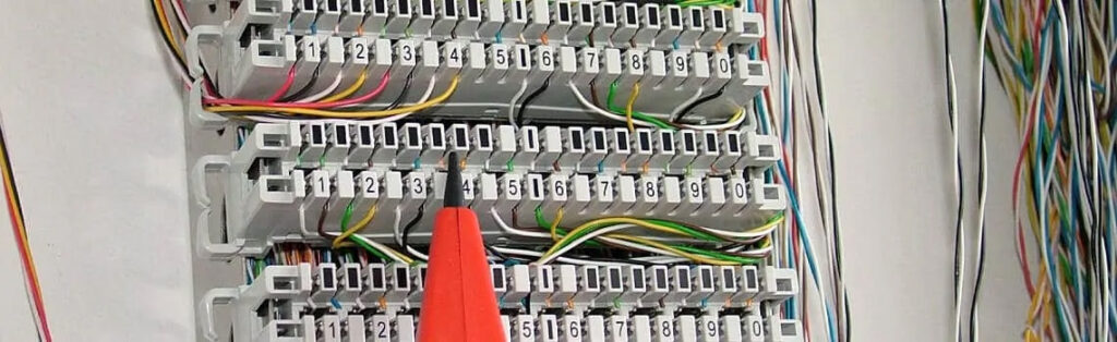
Fig. 1.8: Wire pair identification with a line tracer
Cabling which has no errors is the basis for every high-performance network. Even the best CAT8 LAN cable is useless if there have already been made technical mistakes during the installation of the cable infrastructure (e.g. in the patch panel or at the junction box) or if the cable itself has a fault (e.g. in the plug). Therefore, we now present you the three most important measuring methods for testing twisted pair cables.
But first things first, before you start to unpack your measurement equipment, you should check the cable category to make sure that the installed cables are suitable for the corresponding bandwidth. After that the cable length is taken into account. If both are plausible and the network is not performing as expected, then you should apply the measuring methods of this guide to isolate the source of the error and to fix it.
2.1 Line locator for continuity test

Fig. 1.9: Continuity test with a multimeter
Continuity testers are devices which are located in the low-cost segment as well as in the higher-priced segment. As always, the rule is: “You get what you pay for”. Thus, the cheapest line detectors have neither specialised ICT functions nor protective measures such as overvoltage protection. Continuity detectors signal with a beep if there is an electrical connection between contacts. You can use them to detect short circuits, to check the correct wiring of a cable installation or to detect faults in an existing cable installation.
You can carry out a continuity test with any commercially available multimeter, as it only checks whether there is an electrical connection between point A and B. However, this method has two decisive disadvantages:
- The cable must be shorted at the far end, i.e. double work.
- There is no search signal, so the identification of the wire pair to be shorted in the patch field is cumbersome and time-consuming, since there is more than one cable or wire pair in a telecommunications installation. Furthermore it is often not exactly clear which cable is connected to which socket.
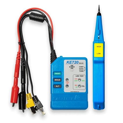
Fig. 1.10: Special line tracer for the Telco sector
For these reasons, we recommend the use of specialised ICT tools such as line tracers. A line tracer consists of a transmitter and a probe. The transmitter, also called toner (tone generator), is clamped to a cable. There are special line tracers for the telecommunications sector, which already come with the normally used connections (RJ11, RJ45), so that they can be connected directly to the corresponding socket. As a consequence professional cable finders save the laborious stripping or re-crimping of plugs (see 1.10).
The toner feeds an acoustic search signal into the electrical wire pair. The probe receives the search signal and emits it acoustically. This allows the cable to be traced even under plaster. You can use this method also to identify a short circuit, since the search signal is only present on the “toner side” of the cable respectively gets terminated at the short circuit point. Therefore the probe can only detect a search signal up to that point and not at the forside.
If there is no short circuit with the probe, you can identify the exact wires carrying the search signal at the open end of a cable. This makes it possible to identify wiring errors even in a multi-core cable. The best line tracers especially for LAN cables include a so-called link blink function. If such toner is connected to a patch cable, the corresponding RJ45 socket in the patch field flashes, so that it can be quickly and easily seen to which socket in the patch field the cable is connected.
Thus, a continuity tester tests the electrical connection between two spots. You can do this with a multimeter, but line tracers are clearly superior in terms of comfort and speed.
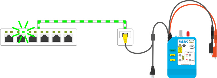
Fig. 1.11: Link blink on the patch field with search signal
2.2 Network tester with wiremap
Network testers are another specialized product category and a perfect complement to a line tracer, as they are able to automatically detect wiring faults without having to short-circuit the far end of the line. Again, there is a wide range of products from pure cable testers for Ethernet cables with a pure point-to-point connection up to extensive network testers with point-to-multipoint connections, integrated TDR and automatic bridge tap detection.
A wiremap is a graphical representation of the cable wires and how they are wired. To create a wiremap, a remote unit is required for the far end. Simply plug one end of the RJ45 cable into the main unit and the other end into the remote unit (or the remote unit into the appropriate patch panel). The main unit sends test signals over all wire pairs, which are then assembled into a wiremap using the remote unit, showing the wiring of a cable.
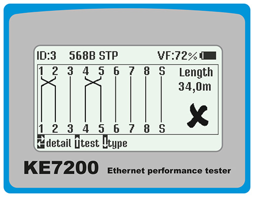
Fig. 1.12: Wiremap
95 % of all cable faults are located either at the beginning or end of the cable, meaning where the cables are connected to sockets and plugs. Cable faults in the middle of the cable are rare. Therefore an integrated TDR function is not necessarily essential, because in most cases it is easy to correct the wires at the cable end points. However, an integrated TDR makes work much easier if the cause of the error is a bend or rupture in the middle of the cable.
2.3 Locating devices (TDR) for fault localisation
Time Domain Reflectometry (TDR) is a method for easy identification and localisation of cable faults. The measuring device emits a pulse signal which is reflected completely or partially when the impedance of the cable changes. Practically it works the same way as a radar. The electromagnetic wave (pulse) moves through the air (the cable) and is reflected when it hits an object, e.g. an aircraft (impedance change, e.g. short circuit). For this reason a TDR is also called cable radar in the German-speaking world. Depending on the fault, different reflection patterns occur, which allow the user to identify the fault.

Abb. 1.13: TDR curves
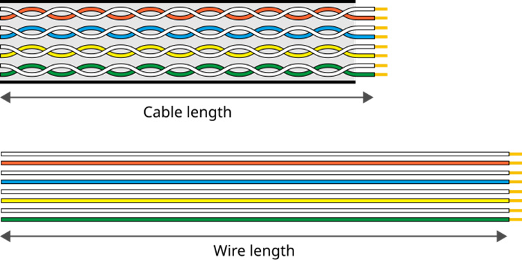
Abb. 1.14: Twisting factor
In addition to the type of fault, a TDR also shows the distance to the fault location, e.g. 1000 m or 15 km. Please note that cable length and wire length can differ, for example if the wires are twisted. Due to the twisting, the wires have to cover more distance than the “straight” cable sheath. Therefore the wires of the cable are longer than the sheath. As a comparison you can imagine the human digestive system, which is between 5.5 m to 7.5 m long, even if the human being himself is only 1.8 m tall.
As a guideline, a deviation of 3 % has proven to be a good estimation, i.e. if the electrical length is 103 m, then the cable length is about 100 m. However, this depends on the cable type or more precisely the twisting factor.
Further information can be found in our post What is a TDR measurement?
3 The difference between verification, qualification and certification
You can test cables in different depths and degrees of regerosity. Basically you differentiate between certification, qualification and verification. By far the most common application is to verify cable installations, i.e. to confirm the functionality of the cable installation. Verification is based on subjective criteria, e.g. “can you make a call via the VoIP connection” or “is the IPTV picture free of errors”. The next stage is the so-called qualification, which proves the functionality of a cable installation on the basis of objective criteria, e.g. by making a load test with a network tester, recording packet losses and creating a measurement protocol by the installation company, which you also often hand over to the customer. The most demanding level for cable testing is certification. This actually only cable manufacturers carry out, who must certify and thus guarantee that a Cat 8 cable also is within the limits specified in the standard, for example, for capacity.
Summary
Testing of ICT installations is a complicated affair and you need a sound knowledge of network cables and installation cables (twisted pair cables) and their category (Cat 1 – Cat 8). However, with the right measuring methods (continuity test, wiremap, TDR) and the appropriate tools (line tracer, network tester, locating device) you can do this quickly and accurately. It is also important to consider in advance whether verification or qualification is sufficient for a network. In practice, certification should only be necessary very rarely.