


In the digital world, the use of the Internet is an important aspect in both private and business environments. Every computer, every smartphone and every printer should be able to communicate with each other, preferably flexibly via Wi-Fi.
The connection of additional devices can lead to various problems, such as the Wi-Fi signal is not strong enough for this. What can be done to amplify the Wi-Fi signal? Which surrounding factors have to be considered exactly.
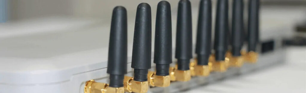
1 How does an antenna work?
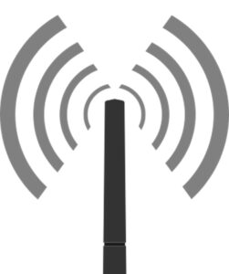
Fig. 1: Antenna with radiation
Why are different radio systems equipped with differently constructed and long antennas? And what difference does it actually make if one or more antennas can be connected to a Wi-Fi router? Why is this extension necessary or is it perhaps just a question of better design? In the following chapter, the topic “antenna technology” is explained in more detail.
1.1 Why are antennas of different lengths?
In wireless communication systems, antennas are used for both the transmitter and the receiver. These vary in length depending on the system. For example, a Wi-Fi antenna is shorter than the antenna of a stationary radio. But why is this the case? Why do communication systems not use the same antenna? The reason is that different frequencies are assigned to different services and systems. Wi-Fi communicates among others in the frequency range of 2.4 GHz or 5 GHz, an FM radio in the frequency range of 87.6 MHz – 108 MHz. The frequency is used to calculate the wavelength, which is decisive for the antenna length. The wavelength can be calculated using the following formula:
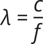
𝛌 corresponds to the wavelength, c to the speed of light and f to the frequency.
| Radio | 95 MHz | 3,15 m |
| Wi-Fi | 2400 MHz | 0,125 m |
Table 1: Frequency and wavelength rounded
Table 1 shows that with increasing frequency the wavelength decreases. To create a good ratio between radiation and reflection, so-called 𝛌/4 radiators are often used for the antenna length.
| Radio | 95 MHz | 3,15 m | ≈ 0,78 m |
| Wi-Fi | 2400 MHz | 0,125 m | ≈ 0,031 m |
Table 2: Antenna length
The antenna length for Wi-Fi with 2.4 GHz thus corresponds to about 3.1 cm. For a radio with 95 MHz, this is 78 cm long for the version according to 𝛌/4. This is the reason why Wi-Fi antennas are shorter than radio antennas.
1.2 How does a Wi-Fi antenna radiate?
The shape of an antenna influences the radiation pattern. The simplest antenna shape is the omnidirectional or rod antenna. With antennas, a distinction is made between horizontal radiation and vertical radiation. The radiation of antennas is shown schematically in diagrams.
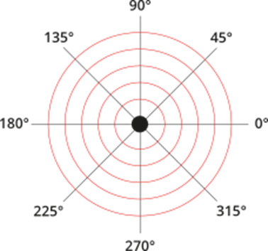
Fig. 2: Horizontal radiation of a rod antenna
With horizontal radiation, the antenna is viewed from above, as shown in Figure 2. In a rod antenna, the electromagnetic waves propagate in a circle around the center of the antenna.
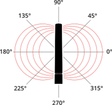
Fig. 3: Vertical radiation of a rod antenna
With vertical alignment, the antenna is viewed from the side. In a rod antenna, the field lines exit one side of the antenna and re-enter the other end of the antenna, as shown in Figure 3. The position of the exit and re-entry depends on the polarity of the antenna.
1.3 Why do Wi-Fi antennas have different shapes?
Antennas are manufactured in different shapes in order to specifically influence the radiation pattern. The antenna is designed to radiate field lines with good directivity. In addition, unused areas are not or only very slightly irradiated. Due to the directivity, the gain of the radiation is higher, accordingly the range in this direction is also higher. In domestic use, simple omnidirectional radiators are used in most cases. The housing of antennas is often designed more modern by the manufacturer, but the content remains an omnidirectional radiator. In companies with large offices or halls, the choice of a different antenna shape can bring great advantages.
In companies with large offices or halls, choosing a different antenna shape can bring great advantages.
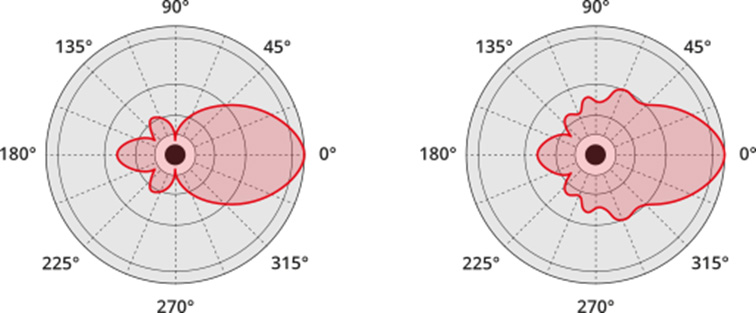
Fig. 4: Radiation pattern, left: vertical alignment, right: horizontal alignment
Figure 4 shows the antenna diagram of a wall antenna. This antenna has clear directional characteristics and, when installed correctly, radiates towards, for example, offices or the hall. The side mounted to the wall, in the diagram on the left, is strongly attenuated.
2 How can the Wi-Fi range be improved?
In the meantime, it has been fundamentally explained how an antenna works. In the following chapter we will discuss the alignment of antennas and why devices are often equipped with more than one antenna.
2.1 How is the Wi-Fi router best positioned?
The position of the router and the connected antennas plays an important role in covering the signal strength in different rooms. It is important to observe the radiation pattern of antennas. Before the router is installed, areas should be defined where Wi-Fi reception should be good and important. The positioning should then be such that the defined areas are illuminated as well as possible.
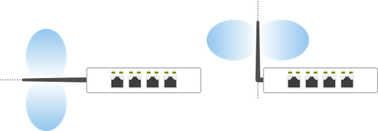
Fig. 5: Wi-Fi antenna alignment
In the case of a router with only one antenna, it must be decided whether the same floor should be served or the rooms directly below/above the router. To avoid this limitation, it is recommended to use a device with more than one adjustable antenna. This allows the coverage area to be extended.
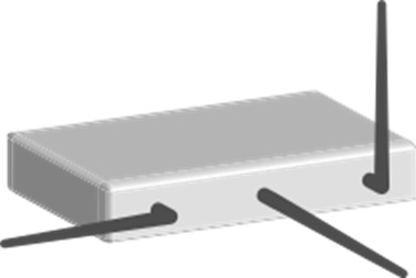
Fig. 6: Alignment of the Wi-Fi antennas with 3 antennas
The use of three antennas creates a good basis. With three antennas, they can be aligned so that each antenna addresses an axis (x, y, z) and the coverage is similar on all levels. To make use of this synergy effect, the router should be placed as centrally as possible in the house or building in order to radiate the resulting field evenly to the surrounding rooms.
2.2 How does a Wi-Fi repeater work?
Depending on the size of the house, building, office or hall, using a single router as a Wi-Fi source may not be sufficient for the required Wi-Fi coverage. The Wi-Fi network near the source is good in principle, but becomes weaker the further away it is from the source. This could be remedied by using a so-called repeater, i.e. a signal amplifier. Wi-Fi repeaters come in various forms and with different connection options.
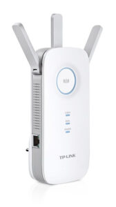
Fig. 7: Wi-Fi repeater
Image by Revon.zhang under the Creative Commons Attribution-Share Alike 4.0 International licence
Wi-Fi repeaters can be integrated for example via a network cable, an existing Wi-Fi or via Power over Line. Power over Line, also known as Powerline, refers to the use of the existing power grid to network end devices.
2.3 Which interferences can influence the Wi-Fi signal?
Wi-Fi is a wireless communication link. In the case of a network cable, excessive pinching of the cable could increase the resistance and reduce the possible performance accordingly. In the case of a radio signal, there is no bruising in this sense, but of course there are other resistances which can also reduce the power. One of the best known interferences in this area are simply walls. Almost every wall attenuates radio signals and weakens them. Put simply, the more walls there are between the transmitter and receiver, the weaker the incoming signal. The respective attenuation of the walls depends on various factors, such as the thickness and the material used. Walls and the architecture of a building are decisive factors when planning wireless networks and have a significant influence on the use of repeaters.
3 How is Wi-Fi reception measured?
Wi-Fi reception depends on various factors. Depending on the area of application, coverage of Wi-Fi reception is, for example, desired or industrially mandatory. The basis is provided by the inventory by simply measuring the Wi-Fi signal. Depending on the specifications, various parameters of this signal are of importance. One of the simplest parameters is the measurement of the signal strength. It becomes somewhat more detailed with an SNR “Signal to Noise Ratio” measurement. This ratio of the useful signal to the noise signal, also known as the signal-to-noise ratio, serves as a measure for assessing the quality of a signal transmission. The selected measurement should always be adapted to the respective requirements and thus always be performed by a specialist and determined with suitable measurement equipment.
3.1 How does a Wi-Fi-Heatmap work?
The Wi-Fi reception strength decreases with distance to the Wi-Fi source. Observation in outdoor areas without interference can be calculated and estimated relatively well. However, in the case of internal building supplies, there are also various interfering influences such as walls or floors. The range is therefore attenuated by these interferences and precisely this attenuation is additionally dependent on the material and thickness of the walls, as already described in section 2.3. In this case a calculation is basically possible, but unfortunately only as good as the definition of the parameters of the walls. This increases the difficulty enormously. A simpler solution would be direct measurement of the signal at different positions in the whole building, the apartment etc. Based on these measurements, it is possible to create a so-called heat map. This heat map shows the reception quality within a colour scale. Areas with good or bad coverage are made directly visible. When viewing a heat map, the focus is therefore on the displayed colours of the areas. The spectrum here ranges from dark green for a very good signal strength to red for a poor supply of radio signals.
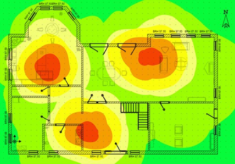
Fig. 8: Wi-Fi Heatmap
3.2 Why is the transmission speed low?
The transmission speed of a wireless application, such as Wi-Fi, can be influenced by various factors. A quick, easy and first step is to measure the signal strength. If the signal strength of the received signal is low, the transmission speed is also reduced.
A disturbance of the signal by electrical objects in the household is also possible. Microwaves, like Wi-Fi, also operate in the 2.4 GHz frequency range and can therefore interfere with or influence individual of the 13 available Wi-Fi channels while they are in operation. It is therefore advisable to examine the channels and, in addition, to change the channel for your own Wi-Fi, which could be a remedy.
AIt is also advisable to take a look at the general distribution of the channels, because in most cases not only your own Wi-Fi is within range, but also external wireless networks from, for example, other residential units, floors or even neighbouring buildings.
When choosing the Wi-Fi channel, the expert should take into account that networks that are too close together can also influence each other and reduce the respective transmission speed. It is therefore advisable to choose a channel for your own Wi-Fi that is sufficiently distant from other existing Wi-Fi networks. The distance should be 4-5 channels so that there is no overlap.
If a simple observation does not provide a cause for a weak transmission speed, a more detailed analysis must be carried out. A measurement option is offered, for example, by using the KE3700/KE3550 MultiTest devices from Kurth Electronic. With the Wi-Fi options of both devices, the following parameters can be viewed at a glance:
- Speed
- Speed strength
- Signal quality
- Data rate RX
- Data rate TX
- Packages RX
- Packages TX
- Packages discarded RX
- Packages discarded TX
- Traffic RX
- Traffic TX
Here you can see measurable Wi-Fi parameters. In addition to the signal strength and speed, more detailed analyses are possible. The analysis is performed in 2 directions. RX corresponds to the receiver “Receiver” and TX to a transmitter “Transmitter”. The analysis of both directions also shows the direction of the origin in case of interference. The value of the rejected packets is an important indicator. The best signal strength is useless if packets are lost during transmission (packet loss) and data is therefore incomplete.
This problem can also occur, for example, when transmitting IP telephony (VoIP) or television via IP (IPTV). Packet losses would be directly audible and/or visible and would not be accepted by the user.
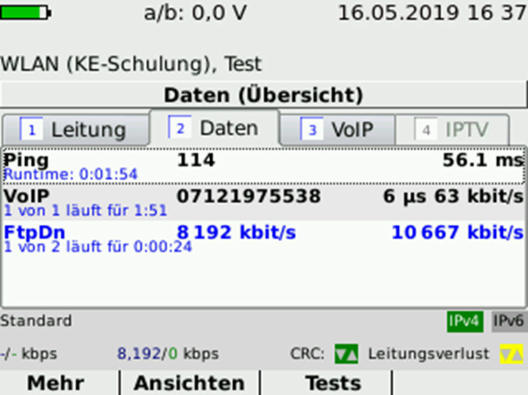
Fig. 9: Wi-Fi function test with the KE3700 xDSL MultiTest
Summary
In this blog post it was described how antennas basically work and why they have different lengths. So the positioning of the Wi-Fi router, the repeater or the antenna play an important role in the received signal strength. The alignment of the antenna for the best possible use of the radiation pattern is also a decisive factor. Commercial WIFI networks should only be planned and tested by a specialist, as there is a lot to consider. A suitable measuring technique is indispensable for displaying quality-relevant parameters and for troubleshooting.